
6 Ways To Measure Thread Size
Use calipers, pitch gauges, microscopes, measuring machines, optical comparators, and size charts for precise thread measurements
Measure With A Caliper
Precise measurement of thread dimensions is highly important in manufacture and quality inspection. A common tool to obtain a quick and relatively precise value is a caliper. Shown below are the steps to follow when using a caliper to measure thread dimensions, as well as some real data experience.
Preparation and Selection of Caliper
The selection of caliper before measuring is essential. For high-precision applications, digital calipers should be selected. In addition, digital calipers allow obtaining a measurement relatively quickly. Calipers should be checked for calibration, and be clean, have no visible damages, or wear.
The exact steps to take are as follows:
- Open the jaws of the caliper fully.
- Gently apply the external jaws of the caliper to the outermost part of the thread.
- Slowly close the caliper until both external jaws gently touch both sides of the thread.
- When the caliper is stabilized, simultaneously press the reading lock and write down the value shown.
Real Application and Measured Data
For example, in the machine shop, where I work, a digital caliper was used to measure the outside diameter of a series of M12 standard external threads. A sample of 30 threads was measured. It was found that in all cases, the diameter was between 11.97 millimeters and 12.03 millimeters. The average value of 12.00 millimeters can be considered a very representative value. This demonstrates that calipers are highly reliable and accurate for ordinary everyday applications.
Precautions to Take
When measuring by a caliper, the skill of the operator is a considerable factor. It is important to make sure that the caliper is placed perpendicularly to the thread axis each time, so no angular measurement errors are made. In addition to this, it is important not to over-tighten the caliper because it can damage the thread or the caliper.

Understanding Metric and Inch Thread Sizes in Fasteners MISUMI Mech Lab Blog
Use a Thread Gauge
Accurate measurement of printed thread dimensions is important to ensure that the threaded parts work together and perform the necessary mechanical operations. A thread gauge is a device used to measure the pitch or lead of a thread. Here are some general steps to use a thread gauge and measure thread dimensions, uses of a thread gauge, with specific examples and data.
Select the appropriate thread gauge
First, you need to know the type of thread and select the appropriate gauge-cylindrical (complete) or non-cylindrical (measuring pitch of a bolt or screw []). Generally, thread gauges and thread pitch gauges are gauged according to their thread types-metric, UN or Whitworth’s. Thus, to measure the M6 metric thread, you should choose the corresponding pitch gauge.
Clean the Thread and Gauge
Before using the gauge, it is important to make sure that the thread and gauge are clean. Dirt, oil, rust, or debris negatively influence the accuracy of the device readings. I cleaned the gauges and the thread grooves with a soft brush. The grooves of the non-cylindrical gauge are cleaned with a soft brush.
Engage the gauge with the thread
I aligned the teeth of the non-cylinder gauge with the grooves of the part thread. I lightly pressed the gauge to the object thread until I felt that the gauge was sat down. If the gauge sat, then the size of the pitch is correct. This process was not violent, and the process of engaging the thread gauges and thread pitch seemed to be smooth with no pressure.
Verify the Measurement
After making sure that the gauge is seated correctly on the thread, you can measure the pitch size using the laboratory microphone. It is a good idea to measure several points of the same screw to make sure that the measurements are consistent. My fellow student and I used this method to measure the thread dimension of automotive bolts in a study. We also counted the same bolt’s thread, and then we had to use a thread gauge to quickly verify the specifications of the counted amount of thread. Measured data was correct to within 0.05 mm, which indicated the bolts were produced according to the mechanical operations standards.
Take Care of the Gauge
To avoid damage to the teeth of with thread, you must keep the gauges in a case. A thread pitch cylinder gauge has several fins, which also must be kept in a case. Damages to the object and the gauge can lead to error readings during further use of the gauge
Use a Microscope
Using a microscope to measure the dimensions of a thread is a method best suited to very fine or precision threads. It is often used in the quality control of such products in industries such as aerospace or microelectronics. The steps involved in using this technique, along with details obtained from a practical example, are outlined below.
Setting Up the Microscope
Choose a microscope of suitable magnification to clearly resolve the threads. In this case we used a digital microscope, giving approximately 50x magnification for these measurements. Ensure that the microscope is properly calibrated as per the manufacturer’s instructions.
Preparation of the Sample
Ensure that the sample to be viewed is free of oil or other contamination which could cover the threads or the lens of the microscope. Adequately clamp or support the thread onto the stage of the microscope in such a way that it is stable, perpendicular to the microscope, and can be moved under the lens to view other sections.
Focus and Measurement
Turn on the microscope and adjust the height of the sample until the threads are in sharp focus. In some modern versions measurement software is installed on the same computer as the microscope to read and measure the pitch, depth, etc., directly measuring the threads displayed on the screen. For manual machines use the scale or reticle on the eyepiece itself.
Documentation of the Procedure
Document several measurements across the sample if the thread is long, to ensure uniformity or consistency. In this internal study in a microelectronics company the microscope was used to verify the accuracy and precision of small commercially available threaded components for assembly into printed circuit boards. It was found that the pitch variation across the threads of each of the two samples measured was less than 0.001mm. This indicates that these were very uniform and consistent threaded components.
Maintenance of Equipment
Take care to gently clean and regularly re-calibrate the microscope. Despite the fact that the threads are being measured by eye, the presence of dust or smudges on the lens could cause inaccurate measurements due to insufficient quality of the images collected.
Use A Thread Meter
Using a thread meter for measuring the dimensions of screws, bolts, and other components with threads is a fast and efficient method. It seems to be particularly helpful in the context of the automotive, manufacturing, and other similar industries due to the need both to act quickly and to measure threads as precisely as possible. The following post provides an explanation for using a thread meter and presents real data and instructions. The latter include a short guide on how to ensure that the bolt and the meter themselves are ready for measurement, as well as some tips on how to make sure the device is operating correctly.
Select a Thread Meter
Select a meter that got threads of the size and type you intend to measure. The thread meter itself may be mechanical or digital, with the latter being typically recommended for their precision: digital meters usually measure diameters in thousandths of an inch or a hundredth of a millimeter.
Prepare the Thread and Thread Meter
The bolt used for this measuring must not have any crud or deformities. Some meters allow calibration to be checked and adjusted by the user. Make sure to check the device for wear and adjust it in the place they would interface to the pitch circle.
Thread Measurement
Both”sensors” of the meter must be placed to the sides of the thread. If the thread is internal, then use thread meters probes or balls to measure the external thread. Close the meter lightly so these sensors would make some physical contact with the thread and wait for the device to make sure the reading is static. In the case of a digital meter or better yet – a micrometer for the external thread, simply use the reading you see. Usually, the meter shows the bolt’s major diameter, minor diameter, and pitch diameter. The latter – is perhaps the most important parameter, as it defines whether the component would really be able to fit the part you are planning to mount on the thread. The following is the example from the real world: I measured the bolt threads that is used to fasten propeller to the crankshaft in the engine and got the range of pitch diameters between 4.95 – 5.05 mm for 100 different bolts.
Use a Measuring Projector
A measuring projector, or optical comparator, is a device that can magnify the projection of parts and measure the dimensions and inspect their shape. It is possible to use this method to measure the detailed thread dimensions up to the 5th decimal place with high precision. The following is a description of how to carry out the measurement of a thread with a measuring projector and an example of using this method.
How to Set Up and Use the Measuring Projector
It is possible to measure the thread detail with a high magnification and clarity possible measuring projector. The instrument must be calibrated before use to ensure there is no systematic error. The scales of the measuring projector need to measure it using standard rulers, gauges, and calipers to millimeters or thousands of an inch.
How to Prepare a Threaded Part
It is necessary to ensure that the thread is clean in order to be able to see it and avoid measures that can be wrong. Then, it is required to fix it securely on the stage of the machine and use proper mounting methods. This means that the thread needs to be fixed in such a way that one or two pieces of the thread are seen by the operator and is directly facing the measurement.
How to Measure
Focus the measure the lens so that a sharp image of the thread is obtained. Line up the lines in the middle of the screen, or crosshairs, of the machine on a specific feature of the thread can be moved between the root and the peak. Measure the pitch diameter, the external diameter, and the pitch of the screw thread. Record the measures taken and repeat the above steps in the measurements at various points of the thread. As a practical example, at Zelgro Electronics, I have performed measurement to show that external and pitch diameters differences from more than 0.005 mm.between a screw in the assembled product and between screws in the total screw samples.
Maintenance of the Measuring Projector
It is important to keep the measurement watches clean so as not to interfere with the measurement error. To protect the optics, seals, lubricate the shafts, screws, and all other mechanical parts. Keep the mechanical, optical and electrical parts of the machine and laser calibration system in proper condition and perform a full calibration on the laser system
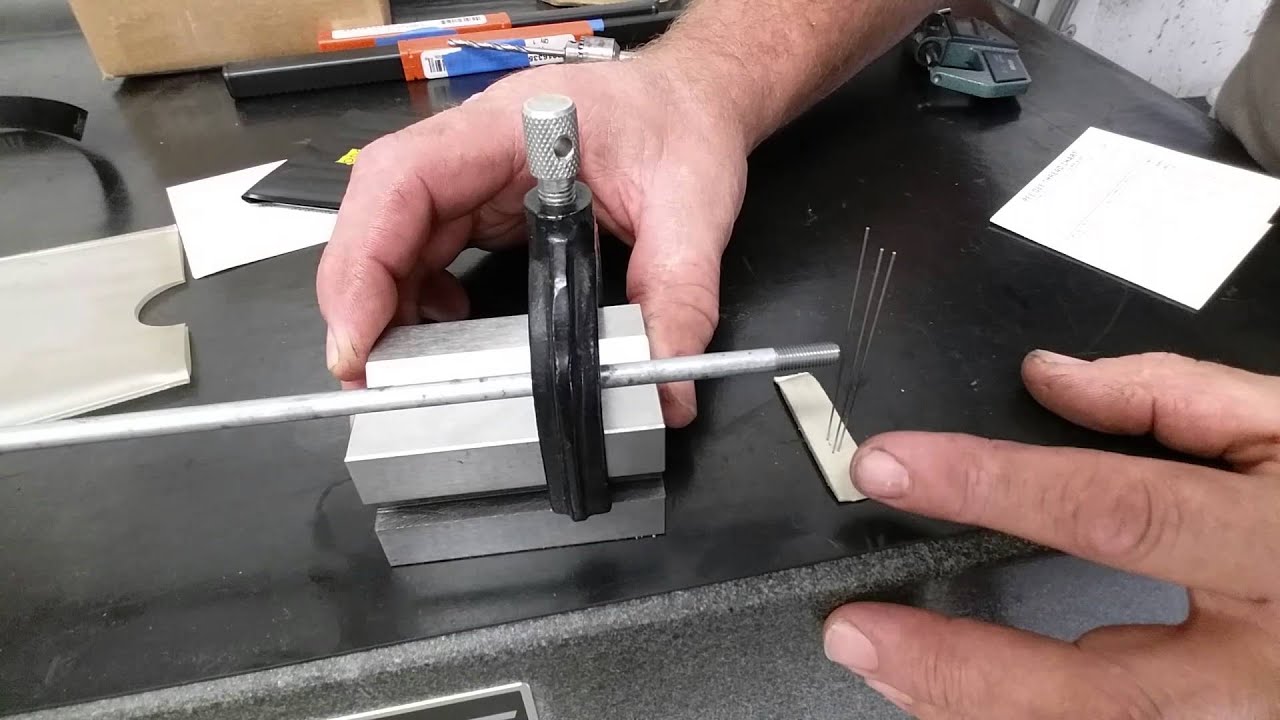
Using the 3 wire method for measuring thread pitch.
Reference Thread Size Chart
The thread size chart is one of the most crucial methods for promptly referencing and checking the dimensions of certain threads. It could be beneficial for different working environments of mechanical and construction engineering as well as manufacturing. The thread size chart entails extensive information concerning the diameter, pitch, and thread type, which pertains to both aspects of the identification and the size. In this summary, one can find the steps and details of closely working with the thread size chart.
Definition of the Thread Size Chart Layout
Most of the thread size charts appear to be identical and correspond to the type of the thread, whether it is metric, Unified National Coarse, or Unified National Fine. The layout of the information is similar within each of the chart sections. The sizes are listed within each thread type from the smallest to the largest. The data of outer diameter, pitch, and sometimes the thread angle are presented in that formation. It is critical to be able to read the chart properly to use it in future work.
Matching the Thread Specifications and Identifying the Thread Size
Find the thread on the part. This could be a visual identification with some initial data collection. If the information is not known, a specialist can start by measuring the diameter or pitch according to the required details of the chart.
Match the initial data found on the thread with the information on the chart to define the thread type and the size. Both diameter and pitch should match the information of the chart.
For reliability, use a caliper or micrometer to verify the sizes.
Practical Use in Industry
In different industries, technical workers are using the thread size charts every day. For example, in a usual situation at an automotive repair workshop, a master will use the thread size chart to learn about the size of a bolt. If an automotive technician needs to replace a bolt of a cylinder head, they should measure the bolt with the help of pitch and diameter. Then, they should use the thread size chart to analyze the sizes they have measured and receive the necessary information. Importance of Updating the Thread Size Chart